| Ignition timing | ||
| Ignition timing. Principles and setting. | ||
| Correct setting of the ignition timing is one of the key factors in achieving reliable starting and efficient running on any motorcycle. A firm grasp of the principles involved and the reasons for the various settings can be helpful in diagnosing problems and carrying out adjustments. | ||
| Basic principles | ||
| Some confusion can arise from the terminology used relating to ignition timing so the following is a brief guide to the
basics. When the spark occurs and the fuel air mixture is ignited the resulting ‘explosion’ drives the piston down the cylinder and the force of the explosion is transmitted to the crank to produce rotary
motion. To produce the maximum effect the piston must be just past the top of the compression stroke as the explosion reaches its full
potential. (and thus correctly positioned to be driven down the cylinder).
It is to achieve this state that the spark is ‘timed’ so that the maximum force is exerted when the piston is in the correct
position.
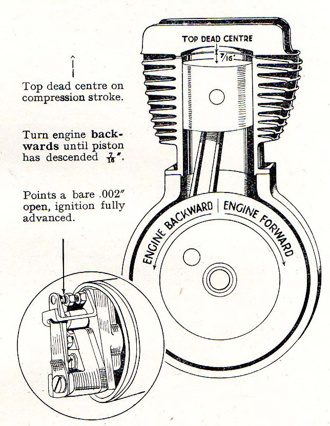
The explosion itself takes a small, but measurable amount of time to reach its full potential after the spark occurs. Due to this slight delay in the explosion reaching its full potential the spark is delivered slightly before, or in ‘ADVANCE’ of the piston reaching the optimum position for power transmission. At engine speeds over about 1000 rpm, despite the variation in piston speeds, this time delay is treated as constant for machines fitted with a manually operated advance and retard, and in the case of the BSA M20 a figure of 7/16” before top dead centre (before the top of the compression stroke) produces the desired result…with the explosion reaching its maximum potential as the piston arrives in the optimum position. So, if the spark is incorrectly set in relation to the piston position and is occurring too early it is too ‘ADVANCED’ and if it is occurring too late it is too ‘RETARDED’. There is also another factor to take into account and that relates to the manually operated advance and retard facility provided. When the spark ignites the mixture the time taken for the explosion to reach its full potential is basically constant at all engine speeds. However, at slow engine revs (under about 1000rpm) the piston is moving far more slowly than it would be at say 5000rpm. Consequently although the explosion time is constant, the time taken for the slow moving piston to reach the ‘optimum’ position is longer and it effectively arrives at the correct position after the explosion has reached its full potential. The manual advance and retard lever provides the solution to this ‘slow speed’ problem. Using the lever the spark can be ‘RETARDED’ ,or made to occur later, allowing the piston the time to arrive at the optimum position. This is the reason why the ‘RETARD’ facility is only ever used at low engine speeds, to aid starting and whilst making slow running adjustments. By modern standards this entire system is regarded a too imprecise. Modern electronic ignition systems progressively and infinitely alter the spark timing throughout the rev range to suit piston speed variations. However, in the case of the older engines, with their low compressions, mild cam timing etc. the system is adequate, if not perfect. |
||
|
|
||
| Preparations before setting the timing. | ||
| As part of a restoration or after carrying outwork on the engine or magneto it will periodically be necessary to
set/reset the ignition timing. This section details the procedures to follow and includes a few hints and tips. I will use the BSA M20 as the example here but the basics apply to all makes, after taking into account the different settings that may be required and the physical differences between engine types. I will also assume in this example that the mag/dyno unit is being fitted to the engine for the first time (e.g after a mag or engine rebuild.) It should be considered ‘best practice’ and the most accurate method to set the ignition timing before refitting the cylinder head during an engine rebuild. Firstly with the mag/dyno off the engine set the maximum points gap to the correct figure (.012”). To do this turn the armature until the points are on the high point of the contact breaker cam and are fully open. Then using the correct mag spanners and a .012” feeler gauge slacken the fixed contact breaker locknut, adjust the contact to give the correct gap (.012”) and retighten the locknut. The next task is to lightly lap the mag drive gear to the taper on the drive end of the mag armature, using some fine grinding paste. This will ensure a good fit of the gear to the shaft and will result in the taper performing its job correctly as a ‘locking’ mechanism when the gear is fitted at a later stage. Use the same method as if lapping in a valve, removing and turning the gear periodically after a little lapping to produce an ‘even’ fit. When a good fit has been achieved by this method carefully clean the end of the armature and the inside of the gear to remove any residual traces of grinding paste. Also take this opportunity to check that the magneto drive gear retaining nut will screw easily onto the armature. If it is a little tight run a tap through the nut and retest. The thread is 3/8BSF. If the nut is still tight carefully dress the armature thread with a knife edged needle file to remove any burrs. If it is necessary to clean up the armature thread with a die set it to be as ‘open’ as possible and progressively take LIGHT cuts to clean the thread. DO NOT use anything more than ‘hand pressure’ on the contact breaker assembly to stop the armature turning. If a spanner is applied here and excessive force is applied permanent damage to the contact breaker end of the armature is likely. The mag/dyno can now be fitted to the mag platform, taking care to position the four locating pegs in the mag base correctly in the slots machined into the platform. Fully tighten the mag/dyno retaining straps. Now refit the mag drive gear and check the mesh of the gear teeth between the mag drive gear and the large intermediate gear. There should be perceptible but minimal free play between the two gears. If the mesh is too tight the fit will need to be adjusted. Overly tight gear meshing will cause a whining sound when running and exerts excessive loads on both the magneto drive end bearing and the intermediate gear bush. To adjust the mesh it will be necessary to remove the mag/dyno and fit shims between the base of the unit and its mounting platform. Shims should be .005” thick. Make these adjustments until a satisfactory meshing of the gears is achieved, not forgetting to fully tighten the mag/dyno straps at each stage and after completion of adjustments. Also remove the drive gear after adjustment. Next refit the ignition advance and retard cable to the handle bar adv/rtd lever and the magneto body, adjusting the free play of the cable using the adjuster at the mag end to give minimal ‘free play’. With the cable fitted and adjusted preparations prior to setting the ignition timing are complete. |
||
| Setting the ignition timing. | ||
| With the mag drive gear removed the engine and the magneto are separated and each can now be set in its correct position. Instructions here assume the cylinder head is not fitted. Instructions for setting timing with the head in place can be found in the last section of this
piece. The correct position for the piston (BSA M20) is 7/16” before top dead centre on the compression stroke
ie. with both valves fully closed and the tappet heads free to rotate.
When it has been determined that the engine is on the correct stroke bring the piston to the top dead centre position (to the top of its stroke). The piston should be flush with the top face of the cylinder in this position but if it is below the top face this distance must be measured (in thousandths of an inch)using a depth micrometer or clock gauge and the figure noted.
If the piston was flush with the top face of the cylinder now set the depth micrometer to 7/16” (.437”). If the piston was, for example .010” below the top face of the cylinder add that amount to the setting. Using the example above the final setting would thus be .447”.
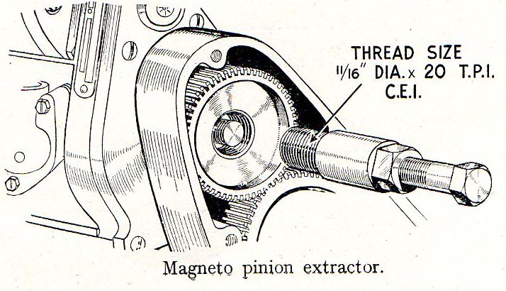
Next turn the engine in the opposite direction to normal running (viewed from the timing side turn the engine anti clockwise) until the piston is approx. 3/4 of the way down the stroke. Place the depth micrometer onto the top face of the cylinder with the shaft protruding into the cylinder. Now slowly turn the engine in the direction of normal running (viewed from the timing side turn the engine clockwise) until the crown of the piston just contacts the depth micrometer. The piston position is now set. The magneto must now be set in the correct position. Timing is set on most machines with the magneto contact breaker cam in the fully advanced position. This can cause some confusion as the design of the magneto was changed post war and a magneto of either type could be fitted. The simple way to determine which type is fitted is from the position in which the adv/rtd cable enters the mag body. Viewing the mag from the contact breaker end, if the cable enters to the right of the contact breaker assembly the contact breaker cam is set fully advanced when the cable is pulled tight by the handlebar adv/rtd lever. If the cable enters the mag to the left of the contact breaker assembly the contact breaker cam is set fully advanced when the cable is slack. Having determined which type is fitted set the contact breaker cam in the fully advanced position with a ‘slack’ or ‘tight’ cable as appropriate. NOTE: Viewed from the contact breaker end the direction of rotation of the magneto when running is clockwise on the BSA M20. On some machines, the Norton 16H for example, the direction of rotation of the mag when running is anti clockwise. In these cases the settings are reversed If the adv/rtd cable enters the mag body to the left of the contact breaker the cam is in the fully advanced position when the cable is pulled tight, if it enters on the right of the contact breaker assembly the the cam is in the fully advanced position when the cable is slack. The contact breakers must now be set so that they are just on the point of opening (this is the point at which a spark is produced). Note that viewed from the contact breaker end the direction of rotation of the mag when running is clockwise. (BSA M20). Turn the magneto in the direction of normal running until the contact breakers are lying at roughly the ‘7 o’clock’ position. The contact breakers will now be fully closed. Carefully lift the moving contact breaker and insert either a .001”-.0015” feeler gauge or a cigarette paper between the contacts. Allow the contact breakers to close again to trap the feeler/paper between the contacts. Now continue to turn the armature slowly in the direction of rotation whilst exerting a small degree of tension on the feeler/paper. At about the 11 o’clock position the contact breakers will start to rise on the contact breaker cam and the feeler/paper will be released. This is the ‘point of opening’ and is the correct setting for the mag. If you are unfamiliar with the procedure some practice may be required to achieve the correct degree of (constant) tension and to set the contact breakers at exactly the right point. Repeat the procedure as necessary until you are sure the mag is correctly set. The ‘cigarette paper’ method is the traditional one and with practice is fairly accurate. However, a modern electronic devise is now available which can achieve the correct result with more certainty. These are advertised in the classic motorcycle press and having bought one I find it a much easier method . It is worth considering the extra expense if your intention is long term ownership. Having now set the mag and the piston in the correct position the next job is to refit the mag drive gear. Once fitted and secured it is not possible to remove the mag drive gear without the correct puller. It is quite possible that the settings may alter during the fitting and tightening of the gear, in which case the process must be repeated. Therefore it is essential to have this tool to hand before proceeding. First carefully replace the mag drive gear, taking care to engage the intermediate gear teeth correctly and to locate the boss on the back of the mag drive gear into the drive gear oil seal. Applying an even pressure push the gear ‘home’ onto the mag armature until it is fully ‘seated’ on the taper. Next, the gear must be driven onto the taper using a hammer and suitable piece of tube (a socket can be used as an alternative). Apply a sharp blow to the end of the tube/socket, taking care to avoid damaging the armature thread where it protrudes through the gear. This will ‘lock’ the gear to the taper. Refit the mag drive gear retaining nut, screwing it fully in by hand. The nut can now be tightened using a suitable ring spanner or socket. Whilst tightening the nut it can be beneficial to use a wide bladed screw driver fitted between the teeth of the mag gear and the intermediate gear to prevent them from turning. Apply slow, even pressure when tightening.
|
||
|
|
||
|
During the final stages of tightening it is likely the engine/mag will rotate a little and it is possible that they will have moved in relationship to each
other. For this reason always check the settings after completion of the
work. Turn the engine over until it is on the compression stroke and the contact breakers are in the 7 o’clock position. Then put the feeler/paper between the contacts as previously described. Also put the preset depth micrometer back in position on the cylinder top face.
Slowly continue rotating the engine until the the feeler/paper is released by the contact
breakers. At this point the piston crown should just be contacting the depth micrometer. If this is the case then the timing is correctly set.
A tolerance of .005”-.010” is acceptable. If the settings have moved during the tightening of the mag drive nut and the mag and piston are not correctly positioned in relation to each other the procedure must be repeated. If this is the case remove the mag drive gear, reset the piston and mag in their correct positions and fit the gear
again. This can be frustrating but is entirely possible and it will often take more than one attempt to achieve the correct result. However, it is essential that the final settings are correct. Setting the ignition timing with the cylinder head fitted. |
||
| Conclusions. | ||
| Correct setting of the ignition timing is vital for the engine to produce the maximum amount of power possible by converting the combustion forces generated in the cylinder into movement of the crankshaft. Any inaccuracies will diminish the amount of usable power produced and increase the amount of wasted heat fed into the structure of the engine. Sidevalve types are particularly susceptible to damage caused by excess heat as the margins of safety in these hotter running engines are smaller .than in OHV types. Retarded ignition timing settings are particularly damaging and the engine should never be run with this condition prevailing. Early failure of the exhaust valve will be the likely result. Many people theorise that ‘near enough is good enough’ when it comes to ignition timing, particularly in the case of sidevalves that are in a low state of tune. However, it is these engines that will be the first to suffer failures if the proper degree of accuracy is not achieved when making these settings. | ||